VGA Controller for an FPGA
Implementation of a VGA Controler using Verilog for an FPGA with both graphics and text mode.
VGA Contoller
VGA stands for Video Graphics Array. A VGA Controller is the main component of Video Signal generator responsible for video signal production. It helps in generating timing of video signals such as horizontal and vertical synchronization signals and blanking interval signals. It may be completely integrated into computing system (video ram on the CPU’s memory map) or as a separate co-processor and can manipulate video RAM independently. It uses analog singal for displaying frames onto the display
VGA Modes
Many different Modes are possible ranging from Standard Text Mode through Standard Graphics Mode to High Definition Graphics Mode
VGA Standard Graphics Mode
VGA Standard Graphics Mode differ by their Resolution, Pixel Clock, their timings, etc. For timing refer VGA Timings or here.
VGA Standard Text Mode
VGA Standard Text Moder differ by their resolution, Pixel Clock, thier timing and also the character size. The most command mode is the 640x480 - 60Hz with Character size of either 8x16 or 8x8 giving a character display of 80x30 or 80x60 respectively. Text Mode can either be in Monochrome or Color depending on the attribute field of the 16-bit character fields.

Note: Bit 15 may be fourth Background color depending on mode.
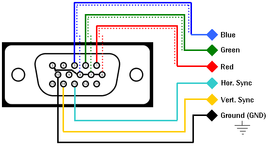
VGA Signal Format and Interfacing
VGA singal consit of 5 major signals (2 sync signals and 3 video signals).
| Signals | Name | Voltage | Description |
|---|---|---|---|
| HSYNC | Horizontal Synchronization | +5V(+3.3V) | Negative pulse denotes the start and of a new line that is makes electron beam restart at next screen’s scanline |
| VSYNC | Vertical Synchronization | +5V(+3.3V) | Negative pulse denotes the start and of frame that is makes electron beam restart at first screen’s scanline |
| R | Red Video Signal | 0 to +0.7V | Red color intensity for current pixel |
| G | Green Video Signal | 0 to +0.7V | Green color intensity for current pixel |
| B | Blue Video Signal | 0 to +0.7V | Blue color intensity for current pixel |
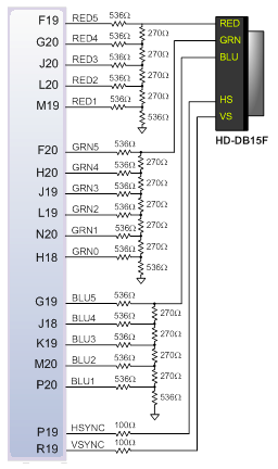
- RGB pins of VGA interface should have analog signal voltage range of 0 to 0.7V depending on the pixel intensity.
- But FPGA has only digital pins of output voltages(0 and 3.3V), a R-2R Digital-to-Analog converter is being used at the output pins for the required RGB pins.
- The cirucit along with 75Ω termination resistance of VGA display to produce analog signal levels for Red, Blue and Green Video signals.
- Here, the FPGA uses 5 bits for Red and Blue channel and 6 bits for Green channel with a possible total color of 65,536 (25 ∗25 ∗26) colors.
- Here, an integrated DAC is used in the FPGA for solving this issue.
Terminologies
- Horizontal Visible area is the duration or the pixel clock count during which the pixels are drawn inside a horizontal line.
- Horizontal Front Porch, Sync Pulse and Back porch are the duration or the pixel clock count during which no drawing of pixels takes places. These timing delays are used for synchronization inside a horizontal Line.
- Horizontal Whole Line is the overall duration in a horizontal line or the overal pixel clock count in a horizontal line. It is the sum of Visible area + Front Porch + Sync Pulse + Back porch.
- Hence the Vertical Refresh Rate or Line Rate is the rate at which each horizontal line gets updated. It is nothing but the inverse of duration of Horizontal Whole Line.
- Vertical Visible area is the duration or the line count during which the horizontal lines are drawn vertically on a frame.
- Vertical Front Porch, Sync Pulse and Back porch are the duration or lines during which no drawing of pixels takes places. These timing delays are used for synchronization.
- Vertical Whole Frame is the overall duration of a frame or the duration it takes to draw all the horizontal lines in a frame. It is the sum of Visible area + Front Porch + Sync Pulse + Back porch.
- Hence the Screen Refresh Rate or Frames per second is the rate at which all the horizontal lines are drawn throughout the frame or rate at which entier frames gets updated. It is nothing but the inverse of duration of Vertical Whole Frame.
Example Timing
Let’s see the example of VGA Standard 640x480 @ 60Hz Industrial Standard.
Horizontal Timing (Line)
| Scanline part | Pixels | Time(μs) |
|---|---|---|
| Visible Area | 640 | 25.422 |
| Front Porch | 16 | 0.635 |
| Sync Pulse | 96 | 3.813 |
| Back Porch | 48 | 1.906 |
| One Horizontal Line | 800 | 31.777 |
Vertical Timing (Frame)
| Frame part | Lines | Time(ms) |
|---|---|---|
| Visible Area | 480 | 15.2532 |
| Front Porch | 10 | 0.3177 |
| Sync Pulse | 2 | 0.0635 |
| Back Porch | 33 | 1.0486 |
| Whole Frame | 525 | 16.6832 |
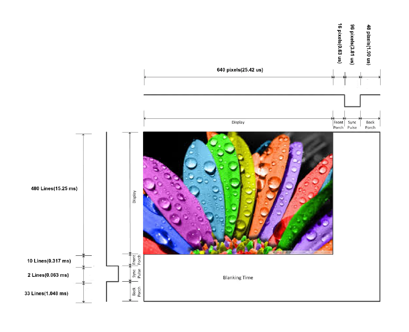
- The pixel clock is 25.175MHz making the duration of each pixel drawn to be 39.721 ns (1/25.175 MHz). 25.175MHz = 39.721ns.
- The pixels are drawn only during the visible area.
- A single horizontal line of 800 pixels (640 + 16 + 96 + 48) takes 800 ∗ (1/25.175 MHz) = 31.777 μs which is about 31.468 kHz making the vertical Refresh Rate.
- A complete frame is made of 800 pixels x 525 lines (480 + 10 + 2 + 33) it would take 800 ∗ 525 ∗ (1/25.175 MHz) = 16.68 ms which is about 60 Hz making the Screen Refresh Rate or the frames per second.
| Pixel Frequency | 25.175MHz |
| Vertical Refresh | 31.468 kHz |
| Screen Refresh Rate | 60 Hz (fps) |
Image to Memory File
The image to be displayed must be converted into a memory files (.mem or .coe) so as that it can be stored in FPGA. Also, an image contains 24-bit pixels (8 for Red, 8 for Green, 8 for Blue). Hence, these pixel values must be converted to the format supported by the DAC of the FPGA (5-6-5 in case of Zybo).
The below script can be used to do the conversion to the required format.
def EightBitsToNBits(adc, N):
    return bin(int((adc * ((2**N) -1)) / 255.0))[2:].zfill(N)
def imgToMemoryFile(fileName='m2.jpg', WH={'W': 240, 'H': 120}, RGBFormat=0):
    # /*
    # RGBFormat
    # 0 - 16bit (5-6-5)
    # 1 - 8bit (grayscale)
    # 2 - 24bit (8-8-8)
    # */
    img = plt.imread(fileName)
    img = cv2.resize(img, (WH['W'], WH['H']))

    if RGBFormat == 0:
        EightBitsToNBits_V = np.vectorize(EightBitsToNBits)
        r = EightBitsToNBits_V(img[:, :, 0], 5).reshape(-1, 1)
        g = EightBitsToNBits_V(img[:, :, 1], 6).reshape(-1, 1)
        b = EightBitsToNBits_V(img[:, :, 2], 5).reshape(-1, 1)
        st = ''
        wt = ''
        for i in range(r.shape[0]):
            st = st + hex(int(r[i][0]+g[i][0]+b[i][0], 2))[2:] + ',\n'
            wt = wt + hex(int(r[i][0]+g[i][0]+b[i][0], 2))[2:] + '\n'
    elif RGBFormat == 1:
        grayImg = cv2.cvtColor(img, cv2.COLOR_RGB2GRAY)
        grayImg = grayImg.reshape(-1, 1)

        st = ''
        wt = ''
        for i in range(grayImg.shape[0]):
            st = st + hex(grayImg[i][0])[2:] + ',\n'
            wt = wt + hex(grayImg[i][0])[2:] + '\n'

    elif RGBFormat == 2:
        r = img[:, :, 0].reshape(-1, 1)
        g = img[:, :, 1].reshape(-1, 1)
        b = img[:, :, 2].reshape(-1, 1)
        st = ''
        wt = ''
        for i in range(r.shape[0]):
            st = st + hex(r[i][0])[2:].zfill(2)+hex(g[i][0])[2:].zfill(2)+hex(b[i][0])[2:].zfill(2) + ',\n'
            wt = wt + hex(r[i][0])[2:].zfill(2)+hex(g[i][0])[2:].zfill(2)+hex(b[i][0])[2:].zfill(2) + '\n'

    with open('./ImageMemoryFile/MemoryFile.coe', 'w+') as f:
        f.write('memory_initialization_radix=16;\nmemory_initialization_vector=\n')
        f.write(st[:-2]+';')
        f.close()
    with open('./ImageMemoryFile/MemoryFile.mem', 'w+') as f:
        f.write(wt[:-1])
        f.close()
The script to convert from image to memory file and from memory file to image can be seen in imageToMemoryConversion.ipynb.
Graphics Mode
The Graphics Mode is used for displaying images onto the display. The Block Diagram for using the graphics mode can be seen below:
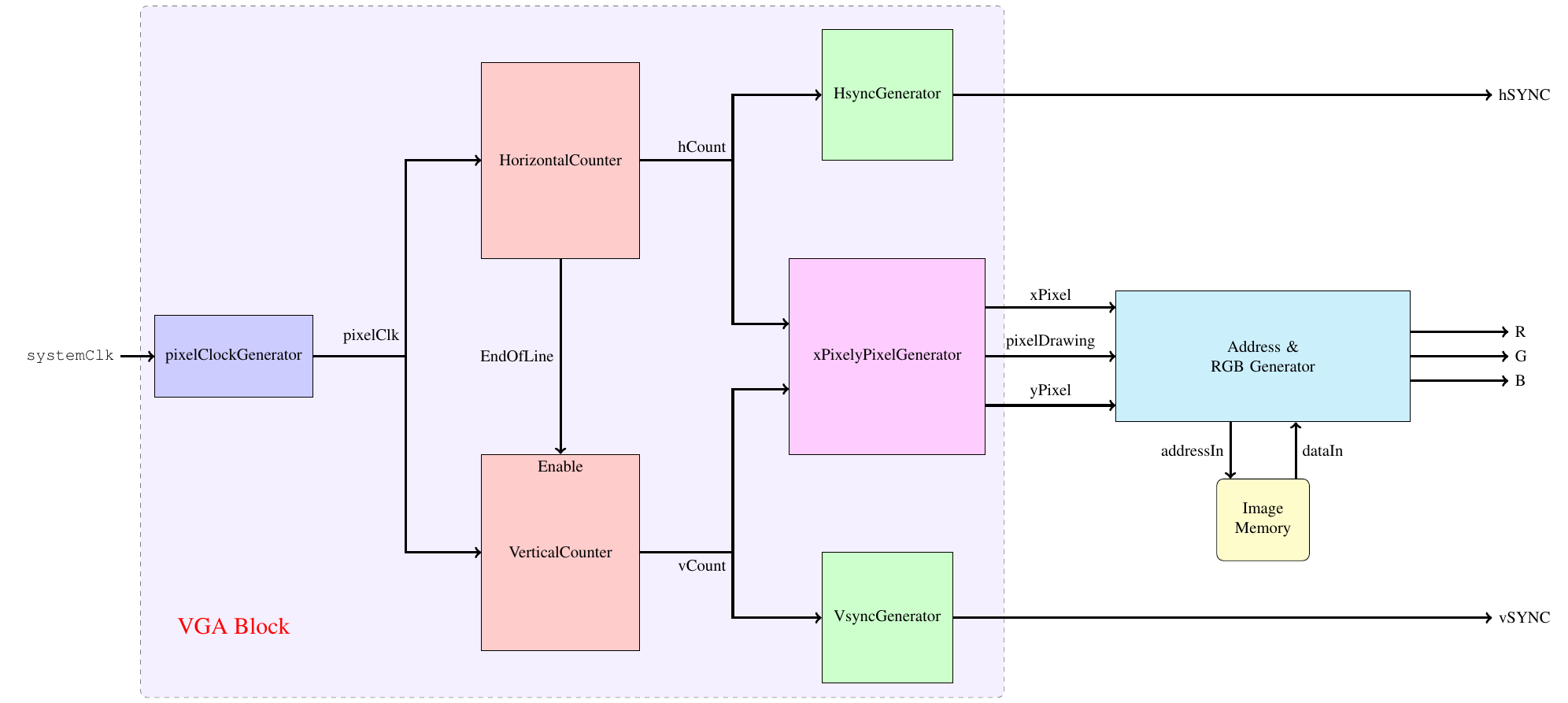
The verilog implementation for a simple Graphics Mode VGA controller to display an image is available here.
Graphics Mode output
The output of Graphics Mode for an image of 640 x 360 with 8-bit (Grayscale) bitformat on a 1024 x 768 resolution display can be seen below:

The output of Graphics Mode for an image of 320 x 180 with 16-bit (5-6-5) bitformat on a 1024 x 768 resolution display can be seen below:

Graphics Mode - Basic Operations
Also, operations such as rotation and scaling were done and controlled with switches available in FPGA. The block diagram for this design is shown below and the source code is available here.
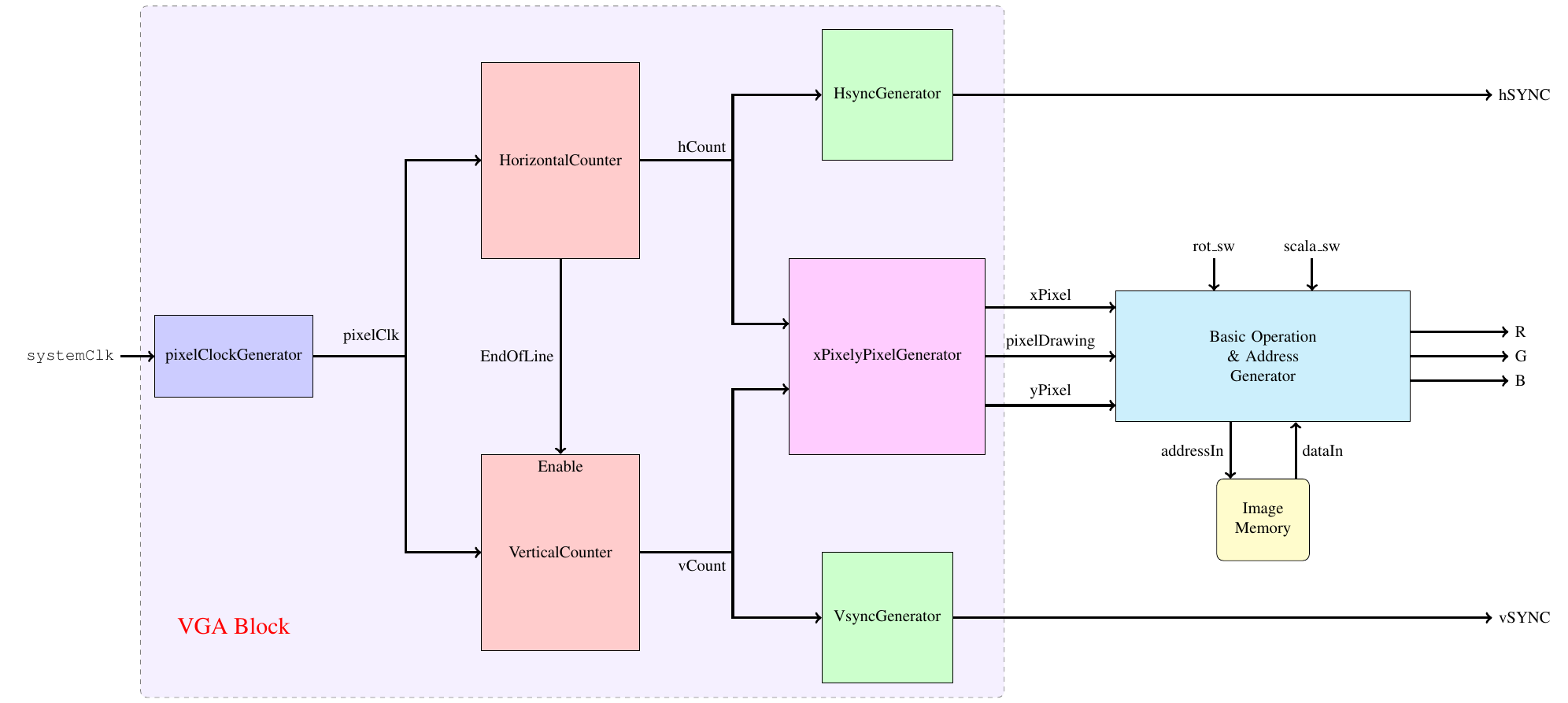
The output for various configuration of input can be seen below.

Text Mode
The Text Mode display characters onto to display. There are a variety of modes for displaying characters depending on the character size, resolution, etc. Here, 8 x 8 characters are used with 640 x 480 resolution giving a Text Resolution of 80 x 40. Hence, a total of 4800 characters can be displayed at a time.
Character ROM
Before going to further processing, a character set must be formed. A script to convert fonts to complete character set with ASCII characters is shown below and is available here. This script gives the memory file for the character ROM which will used to display characters onto the display.
def getCharacterMatrix(character=' ', display=False, fontName = ""):
    font = ImageFont.truetype(fontName, 8)
    width = 8
    height = 8
    im = Image.new("L", (width, height))
    # im = Image.new("1", (width, height), (0, 0, 0))
    draw = ImageDraw.Draw(im)
    draw.text((0, 0), character, 1, font=font)

    if display:
        plt.imshow(im, cmap='gray')
        plt.show()

    gg = np.array(im).flatten()
    st = ''
    for i in range(gg.size):
        st=st+str(gg[i])
    return st

def FontToMem(fontName=''):
    st = ''
    for i in range(0,256,1):
        gg = getCharacterMatrix(chr(i),fontName=fontName, display=False)
        ## reversing as they wer reversed
        st = st + gg[::-1] +'\n'
    with open('./TextModeMemoryFiles/CharacterROM_ASCII.mem', 'w+') as fil:
        fil.write(st[:-1])
        fil.close()


FontToMem("Fonts/family-basic.ttf")
Text Buffer
The Text Buffer is a character memory consisting the index of characters to be displayed onto the screen. These index corresponds to the character ROM addresses. They consist basically the ASCII characters. Creation of Text Buffer for displaying basic text is shown below.
def characterBufferToMem(characterBuffer):
    st = ''
    for i in range(len(characterBuffer)):
        st = st + hex(ord(characterBuffer[i]))[2:].zfill(2) + '\n'
    for j in range(len(characterBuffer), 80*60):
        st = st + hex(ord(' '))[2:].zfill(2) + '\n'
    with open('TextModeMemoryFiles/characterBuffer80x60.mem', 'w+') as fil:
        # print(st[::-1])
        fil.write(st[:-1])
        fil.close()
characterBufferToMem("VGA Controller --- narendiran1996")
The Block diagram for Text Mode to display basic text can be seen below. The verilog implementation of the same is available in VGA_TextMode_HelloWorld.

Text Mode - Output
The outputs of Text mode for a 640x480 resolution with 8x8 characters are shown below.


The complete source code is available here.