UART VGA System
A system for sending image from PC to FPGA through Serial UART and display on a Monitor using VGA. The connection setup used can be seen below:

Components Used
- FPGA (Zybo Zynq-7000)
- USB-UART Converter (FTDI FT232)
- VGA Cable
Development
The System is developed in three stages as described below:
- UART LED System
- Recieve data from PC and display them on the LED in the FPGA
- Send the led status back to the PC
- Application in python to check the working
- UART BRAM System
- Recieve BRAM Depth from PC and store it in the FPGA
- Send the BRAM Depth back to the PC
- Store the data from PC to FPGA through Serial UART
- UART VGA System
- Recieve BRAM Depth from PC and store it in the FPGA
- Send the BRAM Depth back to the PC
- Store the data from PC to FPGA through Serial UART
- Display the BRAM memory as image onto the monitor using VGA
UART LED System
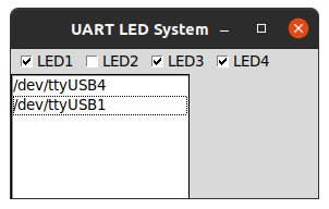
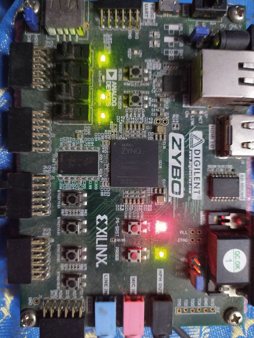
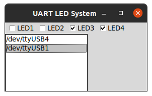
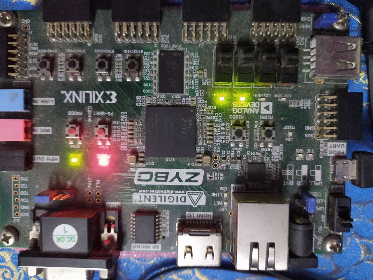
The first stage is where a simple data is transmitted and received between PC and FPGA through UART. A system where the led values are sent to the FPGA through UART and the LED’s glow according to the value. And, also the current led status can be returned back. The source can be seen in UART LED System github page.
The result’s can be seen below:
UART BRAM System
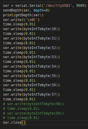
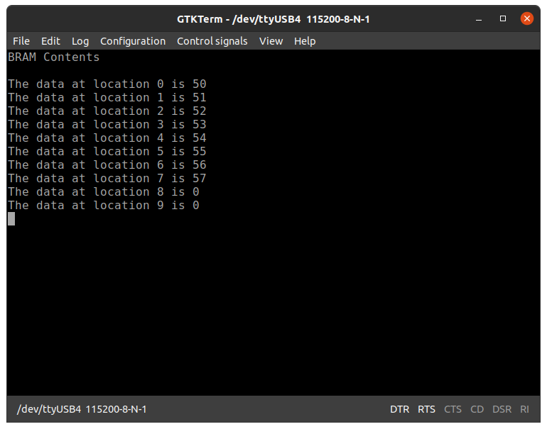
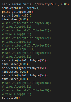
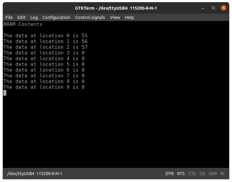
In the next stage, number of data values are sent. A system where the BRAM’s is filled with values sent from PC through UART. The depth of BRAM is also sent. The source can be seen in UART BRAM System github page.
The result’s can be seen below:
UART VGA System
The final stage is where the BRAM’s memory is used by VGA to display the output.Same as BRAM System with the addition of VGA Controller to display the BRAM memory containing an Image. The source can be seen in UART BRAM System github page.
The result’s can be seen below:


Shown below is a gif by which the image is read from BRAM:

The complete source code is available here.